|
|
 |
|
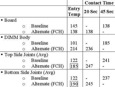
Rework Study SN100C solder was used due to its previously documented lower copper dissolution rate during mini-pot rework compared to SAC305. SN100C has a melting temperature of 227˚C, which is ten degrees higher than SAC305 (217˚C). The solder pot temperature used in the study was 272˚C which is 45 degrees above the melting temperature. Kester RF771 tacky flux was used as its formulation is designed specifically for rework. The solder contact time during PTH rework is multiple times longer than the contact time during wave soldering, therefore the fluxes typically used for wave soldering are not designed to withstand the rework process. Multiple thermocouples were attached to the bottom side and topside DIMM joints as well as to the DIMM body. A baseline thermal profile and an alternate thermal profile were developed. The baseline profile preheated the entire board to 150˚C. The instrumented DIMM was then immersed in solder until all top side joints reached 240˚C, which took forty-five (45) seconds. During the alternative profile, the board was preheated to 150˚C just like the baseline process. However a three (3) minute Focused Convective Heating (FCH) stage took place prior to immersion in solder. During the FCH stage, topside heating from the nozzle and bottom side heating from the universal heating blades increased the top and bottom side joint temperatures by approximately 55˚C. The FCH stage acts like an extended soak stage where the DIMM temperature is increased and stabilized and where the core temperature of the board near the DIMM is maintained. Immersion in solder occured after the FCH process was complete, however the required contact time to achieve 240˚C top side joint temperature was significantly shorter, in this case twenty seconds versus forty-five seconds for the baseline process (table 1).
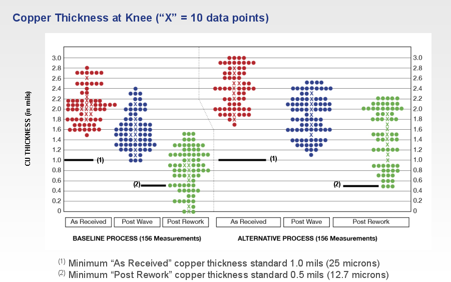
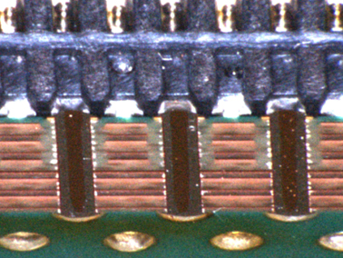
Initial assembly of the test vehicles was done on a standard wave soldering system using SAC305. Kapton tape was used to protect twenty bottom side joints on one end of each DIMM site from wave soldering. These unsoldered joints represented the "as received" copper thickness for each DIMM site. An additional twenty joints were protected from the rework processes. These joints represented the "post-wave" copper thickness for each DIMM site. A total of twenty-six DIMM sites were subject to a complete rework cycle that included removal, barrel cleaning and replacement using either the baseline or alternate process. Reworked TV's were sent to an independent laboratory for cross section analysis. Twelve cross section measurements of the bottom side knee were taken in the "as received", "post-wave" and "post rework" sections on each DIMM site (table 2. "X" represents ten data points).
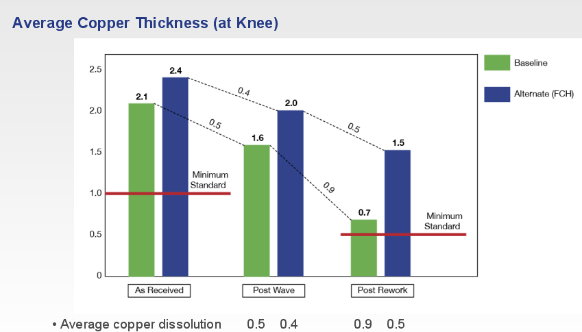
Table 2 shows that the "as received" copper thickness varied from a low of 1.6 mils to a high of 3.0 mils which in turn resulted in a wide variation of both the "post wave" and "post rework" copper thickness. Table 3 is a summary of the average copper thickness and average dissolution based on the data points in Table 2. The key point in Table 3 is that the average "post rework" copper dissolution for the alternate (FCH) process was 0.5 mils compared to 0.9 mils for the baseline process. Convectively heating the DIMM prior to solder immersion resulted in a 45% (0.5 vs 0.9 mils) reduction in copper dissolution. Table 3 also shows that the average "post rework" copper thickness for the alternate (FCH) process was 1.5 mils which is significantly above the minimum standard of 0.5 mils (12.7 microns). Comparatively the average "post rework" copper thickness for the baseline process was only 0.7 mils which is just above the minimum standard. In addition, 22% of the baseline copper thickness measurements fell below 0.5 mils. Tables 2 and 3 clearly show that the alternate (FCH) rework process significantly increases the lead-free PTH rework process window for high complexity assemblies.
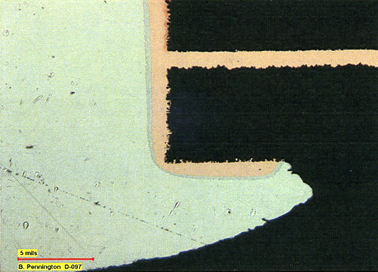
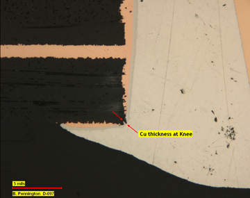
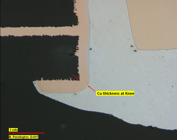
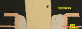
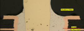
Figure 16 illustrates the typical baseline rework process where significant copper dissolution has occured on the knee, barrel and pad, however the post-rework copper thickness still exceeds the 0.5 mil (12.7 micron) minimum standard. Figure 17 illustrates the worst-case baseline rework process where almost complete copper dissolution occured at the knee. Figure 18 illustrates the typical alternate (FCH) rework process where minimal copper dissolution occured.
|
100% barrel fill was a key objective of the alternate (FCH) process. It was expected thet Focused Convective top side heating of the component would significantly improve barrel fill by creating a heated upward path for the solder to follow. However 100% barrel fill was also achieved in the baseline process where no FCH was used. It was surmised that there were two reasons for the significant improvement in barrel fill during PCBRM100 rework compared to wave soldering. First, the solder contact time during rework is multiple times longer than in the wave soldering process. Second, flux was applied to the bottom side of the board, the top side of the board and onto the replacement component pins during the rework process compared to just the bottom of the board during wave soldering. A "post rework" void analysis was also performed on the one hundred and fifty-six (156) joints that were analyzed. 42% of the joints analyzed had zero voiding, 44% has a worst case void diameter of 10% or less and 14% had a worst case void diameter over 10%.
Summary and Conclusions The "lead in solder" exemption for Class 3 applications including server, storage and network infrastructure equipment expired in 2014. Alternative rework solutions, including convection, IR, vapor phase and laser have been proposed, however none of the existing technologies was designed with lead-free rework of PTH components on large, high thermal mass assemblies in mind. The PCBRM100 is a "clean sheet of paper" design approach to solving copper dissolution and barrel fill issues on Class 3 assemblies. After design and beta testing for over three years, initial production shipments began in the first quarter of 2013.
|
|